1990 Johnson Evinrude "ES" 60 thru 70 Service Manual, P/N 507873, Page 48Get this manual
Synchronization and Linkage Adjustments 65 RS
It is important that this step-by-step procedure be followed in sequence and be performed exactly as written to ensure consistent engine idling and smooth operation throughout the RPM range
The flywheel has two timing gridsBe sure the flywheel grid markedRope" is used for rope start model adjustmentsSet Timing Pointer If the iming point er or intake manifold has been disturbed, check the top dead center timing pointer alignment
1To prevent accidental starting of the engine while servicing, twist and remove all spark plug leads
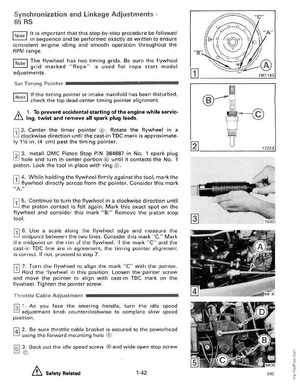
f1l 2Center the timer pointer Rotate the flywheel in clockwise direction until the cast-in TOC mark is approximately 11f2 in(4 cm) past the timing pointerf2l 3Install OMC Piston Stop PI 384887 in No1 spark plug hole and turn in center portion until it contacts the No1 pistonLock the tool in place with ring '11 4While holding the flywheel firmly against the tool, mark the flywheel directly across from the pointerConsider this mark IIA '11 5Continue to turn the flywheel in clockwise direction until the piston contact is felt againMark this exact spot on the flywheel and consider this mark "B Remove the piston stop toolUse scale along the flywheel edge and measure the midpoint between the two linesConsider this markC" Mark the midpoint on the rim of the flywheelIf the mark "C" and the cast -i TDC line are in agreement, the timing pointer alignment is correctIf not, proceed to step 7to align the mark "C" with the pointerHold the flywheel in this position Loosen the pointer screw and move the pointer to al ign with cast-in TDC mark on the flywheelTighten the pointer screwThrottle Cable Adjustment f31 1As you face the steering handle, turn the idle speed knob counterclockwise to complete slow speed position