1990 Johnson Evinrude "ES" 40 thru 55, P/N 507872, Page 110Get this manual
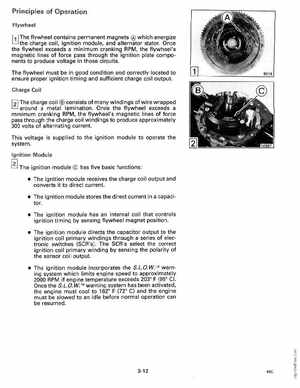
Principles of Operation Flywheel I,l The flywheel contains permanent magnets which energize charge coil, ignition module, and alternator statorOnce the flywheel exceeds minimum cranking RPM, the flywheel's magnetic lines of force pass through the ignition plate components to produce voltage in those circuitsThe flywheel must be in good condition and correctly located to ensure proper ignition timing and sufficient charge coil outputCharge Coil around metallaminationOnce the flywheel exceeds minimum cranking RPM, the flywheel's magnetic lines of force pass through the charge coil windings to produce approximately 300 volts of alternating currentThis voltage is supplied to the ignition module to operate the systemIgnition Module The ignition module has five basic functions: The ignition module receives the charge coil output and converts it to direct current The ignition module stores the direct current in capacitor The ignition module has an internal coil that controls ignition timing by sensing flywheel magnet position The ignition module directs the capacitor output to the ignition coil primary windings through series of electronic switches (SeR's)The SeR's select the correct ignition coil primary winding by sensing the polarity of the sensor coi output The ignition module incorporates the S.L.OWTM warning system which limits engine speed to approximately 2000 RPM if engine temperature exceeds 2030 (950 e)Once the S.L.OWTM warning system has been activated, the engine must cool to 1620 (72 e) and the engine must be slowed to an idle before normal operation can be resumed