1990 Johnson Evinrude 120 thru 140, 185 thru 225, 300 HP, P/N 507875, Page 185Get this manual
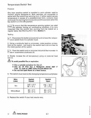
Temperature Switch Test Purpose One heat sensitive switch is installed in each cylinder head to monitor engine temperatureBoth switches are connected in series with the control box warning hornIf either switch senses temperature in excess of predetermined limit, contacts close and cause the warning horn to sound continuous tone when the key switch is in the ON positionTo ensure that the temperature sensing system can alert the operator during an overheating condition, it is very important that the control box warning horn be tested on regular basisSee Warning Horn Test, Section 1Testing f4l 1Disconnect the bullet connector(s) and remove the temperature switch from the cylinder head 2Using continuity light or ohmmeter, make positive connections to the switchone lead to the switch lead and one lead to the metal portion of the switch