1990 Johnson Evinrude 120 thru 140, 185 thru 225, 300 HP, P/N 507875, Page 153Get this manual
1121 STEPSENSOR COIL TEST
Ground Test
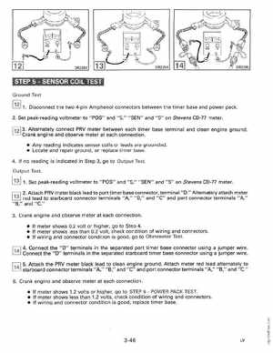
1Disconnect the two 4-pin Amphenol connectors between the timer base and power pack2Set peak-reading voltmeter to "POS" and "5," "SEN" and "5" on Stevens CD-77 meter1,2l 3Alternately connect PRV meter between each timer base terminal and clean engine ground Crank engine and observe meter at each connection Any reading indicates sensor coils or leads are grounded Locate and repair ground, or replace timer base4If no reading is indicated in Step 3, go to Output TestOutput Test1Set peak-reading voltmeter to "POS" and "5," "SEN" and "5" on Stevens CD-77 meterr:;-::;l 2Attach PRV meter black lead to port timer base connector, terminal "D Alternately attach meter red lead to starboard connector terminals "A," "B," and "C" and port connector terminals "A," "B," and "C
3Crank engine and observe meter at each connection If meter shows 0.2 volt or higher, go to Step If meter shows less than 0.2 volt, check condition of wiring and connectors If wiring and connector condition is good, go to Ohmmeter Test