1990 Johnson Evinrude 120 thru 140, 185 thru 225, 300 HP, P/N 507875, Page 119Get this manual
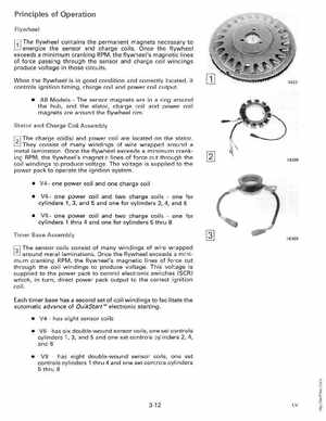
Principles of Operation Flywheel
L!J energize
r.Jl The flywheel
contains the permanent magnets necessary to the sensor and charge coilsOnce the flywheel exceeds minimum cranking RPM, the flywheel's magnetic lines of force passing through the sensor and charge coil windings produce voltage in those circuits
When the flywheel is in good condition and correctly located, it controls ignition timing, charge coil and power coil output All ModelsThe sensor magnets are in ring around the hub, and the stator, charge coil and power coil magnets are around the flywheel rim
Stator and Charge Coil Assembly
t=J They consist of many windings of wire wrapped around a
metal laminationOnce the flywheel exceeds minimum cranking RPM, the flywheel's magnetic lines of force cut through the coil windings to produce voltageThe voltage is supplied to the power pack to operate the ignition system V4one power coil and one charge coil V6one power coil and two charge coilsone for cylinders 1, 3, and and one for cylinders 2, 4, and V8one power coil and two charge coilsone for cylinders thru and one for cylinders thru 8