1988 Johnson Evinrude CC 60 thru 75 outboards Service Manual, Page 125Get this manual
Principles of OperationC.DIgnition Systems Refer to foldout wiring diagramFlywheel
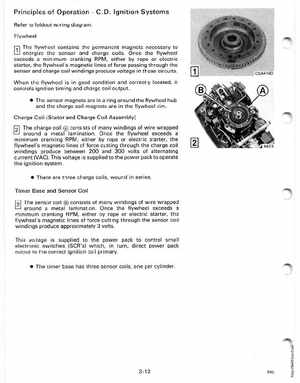
r:;l The flywheel contains the permanent magnets necessary to energize the sensor and charge coilsOnce the flywheel exceeds minimum cranking RPM, either by rope or electric starter, the flywheel's magnetic lines of force passing through the sensor and charge coil windings produce voltage in those circuits
When the flywheel is in good condition and correctly located, it controls ignition timing and charge coil output The sensor magnets are in ring around the flywheel hub and the charge coil magnets are in the flywheel rimCharge Coil (Stator and Charge Coil Assembly) The charge coil consists of many windings of wire wrapped around metal laminationOnce the flywheel exceeds minimum cranking RPM, either by rope or electric starter, the flywheel's magnetic lines of force cutting through the charge coil windings produce between 200 and 300 volts of alternating current (VAC)This voltage is supplied to the power pack to operate the ignition system There are three charge coils, wound in seriesTimer Base and Sensor Coil The sensor coil consists of many windings of wire wrapped around metal laminationOnce the flywheel exceeds minimum cranking RPM, either by rope or electric starter, the flywheel's magnetic lines of force cutting through the sensor coil windings produce approximately voltsThis voltage is supplied to the power pack to control small electronic switches (SCR's) which, in turn, direct power pack output to the correct ignition coil primary: The timer base has three sensor coils, one per cylinder