1987 Johnson/Evinrude CU Outboards 35A thru 55 Service Manual, Page 131Get this manual
Principles of OperationC.DII Ignition System Flywheel
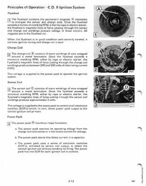
The flywheel contains the permanent magnets necessary to energize the sensor and charge coilsOnce the flywheel exceeds minimum cranking RPM, either by rope or electric starter, the flywheel's magnetic lines of force passing through the sensor and charge coil windings produce voltage in those circuitsAll magnets are in the flywheel rim
When the flywheel is in good condition and correctly located, it controls ignition timing and charge coil outputCharge Coil
111 The charge coil consists of many windings of wire wrapped
around metal laminationOnce the flywheel exceeds minimum cranking RPM, either by rope or electric starter, the flywheel's magnetic lines of force cutting through the charge coil windings produce between 200 and 300 volts of alternating current (VAG)This voltage is supplied to the power pack to operate the ignition system Sensor Coil