1985 OMC 65, 100 and 155 HP Models Commercial Service Manual, PN 507450-D, Page 414Get this manual
20Insert the trim -down pump relief valve and spring into the manifold in the position shown 11241
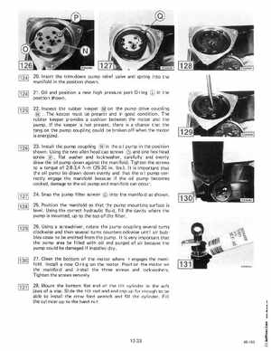
21Oil and position new high pressure port a-ring position shown
22Inspect the rubber keeper on the pump drive coupling The keeper must be present and in good conditionThe rubber keeper provides cushion between the motor and the pumpIf the keeper is not present, there is chance that the tang on the pump coupling could be broken off when the motor is energized23Install the pump coupling in the oil pump in the position shown Using the two allen head cap screws and one hex head screwflat washer and lockwasher, carefully and evenly draw the oil pump down against the manifoldTighten the screws to torque of 2,8-3,4 Nm (25-30 inIbsIt is important that the oil pump be drawn down evenly and that the oil pump correctly engage the manifold because if the oil pump becomes cocked, damage to the oil pump and manifold can occur24Snap the pump filter screen into the manifold as shown25Position the manifold so that the pump mounting surface is levelUsing the correct hydraulic fluid, fill the cavity where the pump is mounted, up to the top of the filter26Using screwdriver, rotate the pump coupling several turns clockwise and then several turns counterclockwise until air bubbles cease to be emitted from the pumpIt is very important that the pump area be filled with oil and purged of air because the pump could be damaged if installed dry27 Clean the bottom of the motor where it engages the mani foldInstall new a-ring on the motorPosition the motor on the manifold and install the three screws and lockwashersTighten the screws secu rely28Mount the bottom flat end of the tilt cylinder in the soft jaws of viseSlide the tilt rod and end cap up far enough to be able to install the crow foot wrench and fill the cylinderFill the cylinder up to the band nut