1985 OMC 65, 100 and 155 HP Models Commercial Service Manual, PN 507450-D, Page 413Get this manual
COA2445
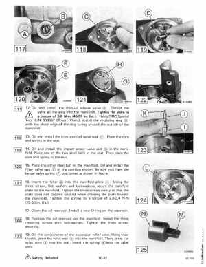
12Oil and install the manual release valve Thread the 'f valve all the way into the manifoldTighten the valve to torque of 5-6 Nm (45-55 inIbsUsing OMC Special Tool PIN 303857 (Truarc Pliers), install the retaining ing with the sharp edge of the ring facing toward the outside of the manifold13Oil and install the trim-up relief valve seat and spring in the seat
Place the core
14Oil and install the impact sensor valve seat in the manifoldPlace one of the two steel balls in the seatThen place the core and spring in the seat
15Place the other steel ball in the manifoldOil and install the filter valve seat in the position shownBe sure you have the longer valve spring positioned as shown in figure 16I nsert the filter into the manifold late Using the three screws, flat washers and lockwashers, secure the manifold plate to the manifoldTighten the three screws evenly so that the plate does not become cocked when drawing the plate toward the manifoldTighten the screws to torque of 2,8-3,4 Nm (25-30 inIbs17Clean the oil reservoir Install new O-ring on the reservoir18Position the oil reservoir on the manifold nstall the three retaining screws with lockwashersTighten the three screws securely19Oil the components of the expansion relief valveUsing your thumb, press the valve seat into the manifold Then, press the valve core Q) into the seatI nsert the spring into the valve core