1985 OMC 65, 100 and 155 HP Models Commercial Service Manual, PN 507450-D, Page 403Get this manual
o C0A2422
C0A2423
C0A2424
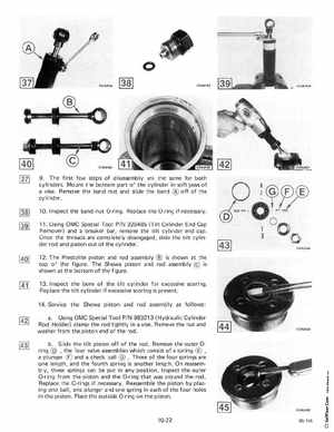
9The firstfew steps of disassembly are the same for both cylindersMount the bottom part of the cylinder in soft jaws of viseRemove the band nut and slide the band off of the cylinder10I nspect the band nut O-ringReplace the O-ring if necessary11Using OMC Special Tool PIN 326485 (Tilt Cylinder End Cap Remover) and breaker bar, remove the tilt cylinder end capOnce the threads are completely disengaged, slide the tilt cylinder rod and piston out of the cylinder12The Prestolite piston and rod assembly is shown at the top of the figureThe Showa piston and rod assembly is shown at the bottom of the figure13Inspect the bore of the tilt cylinder for excessive scoringReplace the tilt cylinder if excessive scoring is present14Service the Showa piston and rod assembly as followsaUsing OMC Special Tool PIN 983213 (Hydraulic Cylinder Rod Holder) clamp the rod tightly in viseRemove the nut and washer from the piston end of the rod bSlide the tilt piston off of the rodRemove the outer ringthe four valve assemblies which consist of spring plunger and check ball Three of the four springs are one length, and the fourth spring is another length On reassembly, these springs can be put in any positionInspect the outer O-ring from the piston and the O-ring that was around the rodReplace the O-rings if necessaryReassemble the piston by placing one ball, one plunger and one spring in each of the four holes in the pistonPlace the outside O-ring on the piston