1985 OMC 65, 100 and 155 HP Models Commercial Service Manual, PN 507450-D, Page 395Get this manual
Troubleshooting the Electrical System 100 and 155
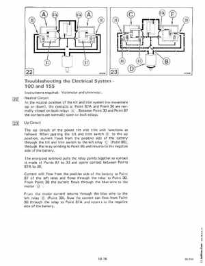
Instruments required: Voltmeter and ohmmeterNeutral Circuit the neutral position of the tilt and trim system (no movement up or down), the contacts at Point 87A and Point 30 are normally closed on both relays Between Point 30 and Point 87 the contacts are normally open on both relaysUp Circuit The up circuit of the power tilt and trim unit functions as follows: When pushing the tilt and trim switch to the up position, current flows from the positive side of the battery through the tilt and trim switch to the left relay (Point 86), through the relay winding to Point 85 and returns to the negative side of the batteryThe energized solenoid pu lis the relay points together so contact is made at Points 87 to 30 and opens contact between Points 87A to 30Current will flow from the positive side of the battery to Point 87 of the left relay and flows through the relay to Point 30From Point 30 the current flows through the blue wire to the motor From the motor current returns through the blue wire to the left relay (Point 30)Now the current can flow from Point 30 through the relay to Point 87 and returns to the negative side of the battery