1985 OMC 65, 100 and 155 HP Models Commercial Service Manual, PN 507450-D, Page 297Get this manual
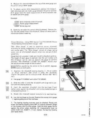
4Measure the clearance between the top of the shim gauge and the pinion using feeler gauge5To obtain correct shim measurement, subtract the measurement obtained with the feeler gauge bet ween the pinion and the shim gauge from the total measurement of shims between the driveshaft and shim gaugeExample0.020" Shim thickness under driveshaft0.017" Feeler gauge measurement 0.003" Shims required 6Carefully set aside the correct shim(s) selected Remove the nut and the pinion from the driveshaftCheck all shims with micrometer before installing Pinion ShimmingUsing OMC Special Tool PIN 393185 (Pinion Thrust Bearing Universal Shim Gauge)100 This "Shim Gauge" is used to determine correct driveshaft shimming for proper engagement of the pinion into th forward and reverse gearsThe "Shim Gauge" consist of basespring screw, one set of driveshaft adapter collars and one set of sh im gauge barsGauge bars are precis ion made and should be handled carefully The length of each gauge is stamped near the part number and this dimension can be used to measure the gauge to confirm accuracyThis dimension is 0,508 mm (0.020"shorter than the actual shimmed length of the dr iveshaftINotel Before assembling the pinion to the driveshaft, degrease tapers on both parts1Assemble the driveshaft bearing housingthrust washerthrust bearingand pinion onto the driveshaftTighten the pinion nut to torque of 8090 Nm (6065 ftIbs