1985 OMC 65, 100 and 155 HP Models Commercial Service Manual, PN 507450-D, Page 234Get this manual
COB136B
COB1369
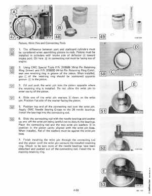
Pistons, Wrist Pins and Connecting Rods 1The difference between port and starboard cylinders must be considered when assembling pistons to rodsPistons must be installed in cylinders with intake side of deflector toward intake portOil hole in connecting rod must be facing top of engine2Using OMC Special Tools PIN 318599 (Wrist Pin Retaining Ring Driver) and PIN 318600 (Wrist Pin Retaining Ring Cone), seat one retaining ring in groove of the pistonWhen installed, gap of the retaining ring should be positioned opposite groove in the piston3Oil and push the wrist pin into the piston opposite where the retaining ring is installedDo not allow the wrist pin to enter cavity of the piston4SI ide one of the wrist pin washers down on the wrist pinPosition flat side of the washer facing the piston5Position top end of the connecting rod over the wrist pinApply OMC Needle Bearing Grease to the 28 needle bearingsI nstall the bearings into the connecting rod6Slide the connecting rod with the needle bearings and washer up and off the wrist pin being careful not to disturb the bearingsPlace the connecting rod and the two wrist pin washers in position in the piston cavity aligned with the wrist pin bossWhen installed, flat of the washers must be against the wrist pin boss7Finish installing the wrist pin through the connecting rod and the piston until the wrist pin contacts the installed retaining ringCheck to be sure none of the needle bearings have been disturbed and pushed out of the connecting rodInstall the remain ng retaining ring