1985 OMC 65, 100 and 155 HP Models Commercial Service Manual, PN 507450-D, Page 220Get this manual
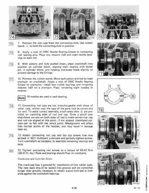
7Remove the rod caps from the connecting rodsUse rubber bands to hold the connecting rods in position8Apply coat of OMC Needle Bearing Grease to connecting rod bearing area Place one retainer half and eight needle bearings on each rod9With pistons and rods pushed down, place crankshaft into position on cylinder block, aligning main bearing with dowel pin in cylinder block, and rotating crankcase heads slightly to prevent damage to the O-rings10Remove the rubber bandsMove each piston and rod to meet crankpin on crankshaftApply coat of OMC Needle Bearing Grease to crankpinsI nstall two needle bearings and remaining retainer half on crankpin Place remaining eight needles in retainer Note18 needles are used in each bearing11Connecting rod caps are not interchangeable with those of other rods, neither may the caps of the same rods be turned end for end To assist correct assembly, small raised dots are provided on matching sides of rod and capDraw pencil over chamfered corners on both sides of rod to make certain that cap and rod are aligned at this pointIf not aligned, chamfered corners can be felt with the pencil pointMisalignment will affect free normal action of the needles, and may result in damage later on 12Attach connecting rod cap and dip cap screws (use new screws) in 501 Outboard Lubricant and partially tighten screwsTurn crankshaft as necessary to assemble remaining bearings and caps13Tighten connecting rod screws to torque of 40-42 Nm (29-31 ftIbs Rods and bearings should float on crankpinsCrankcase and Cylinder Block The crankcase face is grooved for installation of two rubber sealsThe new seals should be seated into grooves and are somewhat longer than actually necessary to obtain good butt seal at both ends against the crankshaft bearingsE u