1985 OMC 65, 100 and 155 HP Models Commercial Service Manual, PN 507450-D, Page 218Get this manual
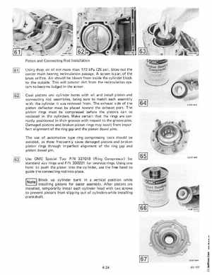
Piston and Connecting Rod Installation Using shop air of not more than 172 kPa (25 psi), blowout the center main bearing recircu lation passageA screen is part of the brass orificeAir should be blown from inside the cylinder block to the outsideThis will prevent dirt from the recirculation system to become lodged in the screenCoat pistons and cylinder bores with oil and install piston and connecting rod assemblies, being sure to match each assembly with the cylinder it was removed from The exhaust side of the piston deflector must be placed toward the exhaust portThe piston rings must be compressed before the pistons can be replaced in the cylindersMake certain that the rings are correctly positioned in their grooves with respect to the groove pinsDamaged pistons and broken piston rings may result from imperfect alignment of the ring gap and the piston dowel pinsThe use of automotive type ring compressing tools should be avoided, as these frequently cause damaged pistons and broken piston ri ngs th rough imperfect alignment of the ring gap and piston dowel pin Use OMC Special Tool PI 327018 (R ing Compressor) for standard size rings and PIN 330221 for oversize ringsUsing one hand to push the piston into the cylinder, use the free hand to guide the connecting rod into placeBlock up cylinder bank in vertical position while installing pistons for easier assemblyAfter pistons are installed, temporarily install each cylinder head with two screws to prevent pistons from slipping out of cylinders while installing crankshaftCO B1 360