1985 OMC 65, 100 and 155 HP Models Commercial Service Manual, PN 507450-D, Page 184Get this manual
Stator and Timer Base Assembly Removal 100 Models 1"" To prevent accidental starting of motor disconnect the charge coil connection (two-wire connector)2Remove flywheelSee Flywheel Removal
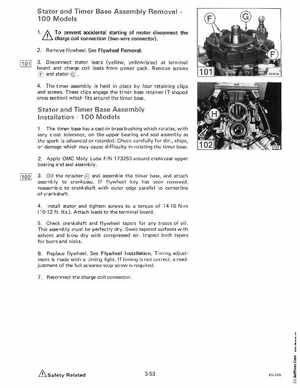
3Disconnect stator leads (yellow, yellowgray) at terminal board and charge coil leads from power packRemove screws and stator 4The timer assembly is held in place by four retaining clips and screwsThese clips engage the timer base retainer (T-shaped cross section) which fits around the timer base
Stator and Timer Base Assembly Installation100 Models
1The timer base has cast-in brass bushing which rotates, with very close tolerance, on the upper bearing and seal assembly as the spark is advanced or retardedCheck carefully for dirt, chips, or damage which may cause difficulty in rotating the timer base2Apply OMC Moly Lube PIN 173250 around crankcase upper bearing and seal assembly3Oil the retainer and assemble the timer base, and attach assembly to crankcaseIf flywheel key has been removed, reassemble to crankshaft with outer edge parallel to centerline of crankshaft4Install stator and tighten screws to torque of 14-16 Nm (10-12 ftIbsAttach leads to the terminal board5Check crankshaft and flywheel tapers for any traces of oilThis assembly must be perfectly drySwab tapered surfaces with solvent and blow dry with compressed airInspect both tapers for burrs and nicks6Replace flywheelSee Flywheel InstallationTiming adjustment is made with timing lightIf timing is not correct, readjustment of the full advance stop screw is required7Reconnect the charge coil connector