1985 OMC 65, 100 and 155 HP Models Commercial Service Manual, PN 507450-D, Page 172Get this manual
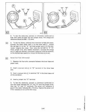
3To test the resistance, connect an ohmmeter (calibrated to high ohm scale) between the two jumper wiresThe charge coil resistance should be 560 75 ohms4To test for shorts, calibrate the ohmmeter to high ohm scaleConnect the black meter lead (-) to the timer base Attach the red lead (+) to the" A" terminal jumper wire in he connectorObserve the meterThen move the red lead to "8" terminal jumper wireAny needle movement indicates the charge coil or leads are shortedA shorted charge coil must be replaced, or the shorted lead repaird to remove the shorted condition Sensor Coil Test (Ohmmeter) 1Separate the four-wire connector between the timer base and power pack2Insert jumper wire in "A" terminal of the timer base end3I nsert jumper wire in terminal "8" in the timer base end of the connector