1985 OMC 65, 100 and 155 HP Models Commercial Service Manual, PN 507450-D, Page 144Get this manual
Capacitor Charge Circuit
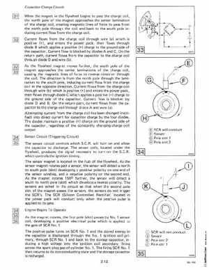
When the magnet in the flywheel begins to pass the charge coilthe north pole of the magnet approaches the center lamination of the charge coil, creating magnetic lines of force to pass from the north pole through the coil and back to the south pole inducing current flow from the charge coilCurrent flows from the charge coil through wire (a) which is positive (+), and enters the power pack, then flows through diode which applies positive (+) charge to the ground side of the capacitorCurrent flow is blocked by diodes and COn the return path, current flows from the capacitor to the charge coil through diode and wire (b) As the flywheel magnet moves furtherthe south pole of the magnet approaches the center laminations of the charge coil, causing the magnetic lines of force to reverse direction through the coilThe direction is from the north pole through the lami nation to the south pole, inducing current flow from the charge coil in the opposite directionCurrent flows from the charge coil through wire (b) which is positive (+) and enters the power pack, then flows through diode which applies positive (+) charge to the ground side of the capacitorCurrent flow is blocked by diode and BOn the return path, current flows from the capacitor to the charge coil through diode and wire (a) Alternating current from the charge coil has been changed (recti fied) into direct current for capacitor charge by the four diodes The diodes maintain positive (+) charge on the ground side of the capacitor, regardless of the constantly changing charge coil output