1985 OMC 65, 100 and 155 HP Models Commercial Service Manual, PN 507450-D, Page 143Get this manual
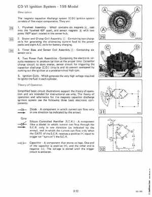
CD VI Ignition System155 Model Description The magneto capacitor discharge system (CD ignition system consists of five major componentsThey are: 1Flywheel AssemblyWhich contains six magnetscast into the flywheel 600 apart, and sensor magnets with two poles 150 apart located in the center hub2Stator and Charge Coil AssemblyContaining two charge coils for generating the alternating current feed to the power packs and eight A.Ccoils for battery charging3Timer Base and Sensor Coil AssemblyContaining six sensor coils4Two Power Pack AssembliesContaining the electronic circu its necessary to produce ign ition at the proper time: Capacitor charge circuit to store energy, sensor circuit for triggering the capacitor discharge (C.D circuits and to prevent overspeed by cutting out the ignition at predetermined high rpm5Ignition CoilsWhich generate the very high voltage required to ignite the fuel in each cylinderTheory of Operation Simplified basic circuit illustrations support the theory of operation and are intended for instructional use onlyThe theory of operation and schematics for the magneto capacitor discharge ignition system use the following three basic electronic components: Diodecomponent in which current can flow only in one direction (as indicated by the arrow)Gate Silicon Controlled Rectifier (S.C.Rcomponent (like diode) in which current can flow through the S.CRonly in one direction (as indicated by the arrow), and in which the current can flow only when the GATE of the S.C.Rreceives positive (+) input to trigger (or "turn-on") the S.C.R