1985 OMC 65, 100 and 155 HP Models Commercial Service Manual, PN 507450-D, Page 142Get this manual
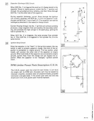
Capacitor Discharge (CD) Circuit When SCR No.1 is triggered the positive (+) charge stored in the capacitor flows to engine ground, enters the No.1 ignition coil through the grounded primary winding, and then flows through SCR No.1 to the other side of the capacitorDuring capacitor discharge, current flows through the ignition coil primary windings and SCR No.1 until the capacitor is discharged and SCR No.1 turns itself offThe capacitor can now be recharged as described in the capacitor charge circuitCurrent flowing through the No.1 ignition coil primary winding produces large magnetic field surrounding the secondary winding, and produces the high voltage to the spark plug, igniting the fuel in cylinder No.1When SCR No2 is triggered, the same process fires cylinder No.2Then SCR No .3 is triggered to fire cylinder No.3 in the same mannerIgnition Stop Circuit Since the capacitor is the "heart" of the ignition system, the key switch is used to prevent capacitor chargeOne end of the capacitor is connected to engine groundThe key switch, when closed, will connect the other end of the capacitor to engine groundWhen both ends of the capacitor are connected to engine ground, current flow from the charge coil will bypass the capacitorWhen the capacitor is not "charged," ignition cannot occur8321 5