1985 OMC 65, 100 and 155 HP Models Commercial Service Manual, PN 507450-D, Page 139Get this manual
Ignition System65 and 155 Models Connector Plugs
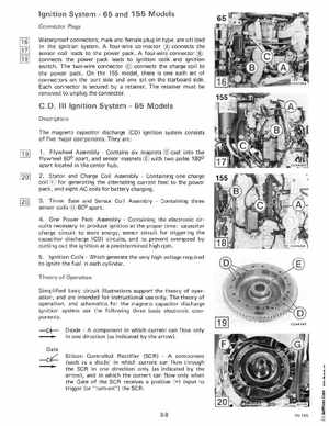
Waterproof connectors, male and female plug-in type, are utilized in the ignition systemA four-wire connector connects the sensor coil leads to the power packA four-wire connector connects the power pack leads to ignition coils and ignition switchThe two-wire connector connects the charge coil to the power packOn the 155 model, there is one such set of connectors on the port side and one set on the starboard side Each connector is secured by retainerThe retainer must be removed to unplug the connector
C.DIII Ignition System65 Models
Description The magneto capacitor discharge (CD) ignition system consists of five major componentsThey are: 1Flywheel AssemblyContains six magnets cast into the flywheel 60 apart, and sensor magnets with two poles 180 apart located in the center hub2Stator and Charge Coil AssemblyContaining one charge coil for generating the alternating current feed to the power pack, and eight AC coils for battery charging
3Timer Base and Sensor Coil AssemblyContaining three sensor coils 60 apart4One Power Pack AssemblyContaining the electronic circuits necessary to produce ignition at the proper time: capacitor charge circuit to store energy, sensor circuit for triggering the capacitor discharge (CD) circuits, and to prevent overspeed by cutting out the ignition at predetermined high rpm5Ignition CoilsWhich generate the very high voltage required to ignite the fuel in each cylinderTheory of Operation Simplified basic circuit illustrations support the theory of operation, and are intended for instructional use onlyThe theory of operation, and schematics for the magneto capacitor discharge ignition system use the following three basic electronic components: