1981 Johnson/Evinrude 4HP Outboards Service Manual, Page 32Get this manual
1Secondary winding 2Condenser 3Points open
Figure 4-4Points Open
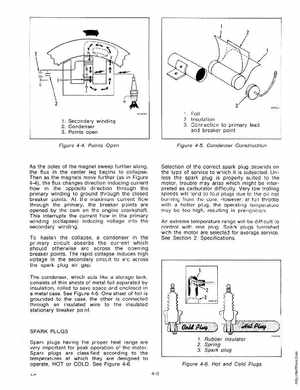
1Foil 2Insulation 3Connection to primary lead and breaker point
Figure 4-5Condenser Construction
As the poles of the magnet sweep further along, the flux in the center leg begins to collapseThen as the magnets move further (as in Figure 4-4), the flux changes direction inducing current flow in the opposite direction through the primary winding to ground through the closed breaker pOintsAt the maximum current flow through the primary, the breaker points are opened by the cam on the engine crankshaftThis interrupts the current flow in the primary winding (collapses) inducing voltage into the secondary windingTo hasten the collapse, condenser in the primary circuit absorbs the current which should otherwise arc across the opening breaker pointsThe rapid collapse induces high voltage in the secondary circuit to arc across the spark plug air gapThe condenser, which acts like storage tank, consists of thin sheets of metal foil separated by insulation, rolled to save space and enclosed in metal caseSee Figure 4-5One sheet of foil is grounded to the case, the other is connected through an insulated wire to the insulated stationary breaker point