1980 Johnson 4HP Service Manual, Page 47Get this manual
Next, the clamp top of the ture plate retaining the leadsSee Figure 4-38 73' 70
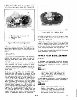
Figure 4-40Coi Locating Ring
1Outside edge of charge coil 2Machined boss 3Clamp
Figure 4-39Coi Locating Bosses
Install the clamp top of the armature plate to position the charge coil and sensor co il leadsSee Figure 4-39
fWith the screws securing the charge sensor coil removedpull the coil and lead assembIy from the insulation sleeve and armature plateNSTALLATION Lubricate the insuation sleeve with sopropyl alcoho and insert the leads through the armature pate and sleeve to the four wire connectorInstall the terminals into the connectorSee wiring diagram for correct location of leadsPosition the charge coil sensor coi the armature plate and insert the screws just finger tightdlocating of the coil assembIy is govmachined mounting surfaces the erned armature plateThe outside edge of the charge and sensor must flush with the chined surfaces the armature plate to contact with the flywheel magnet and vide maximum output from the coilsSee Figure 4-39Aignment of the charge coil and sensor coil will simplified when using the Coil Locating Ring (Special No317001) chined to fit the armature plate bossesSee Figure 4-40With the Coil Locating Ring in posithe armature plate bosses, push the tion ring toward the while pulling the coi toward the ringand tighten the coil mounting screws to the torque specified in Section 24-18