1979 Evinrude 4 HP Outboards Service Manual, PN 5424, Page 31Get this manual
After the capacitor is charged, the flywheel continues to rotate so the magnetic field of magnet passes through the sensor coil windingproducing alternating currentCurrent leaves the sensor coil through wire (a) which is positive (+), and enters the power packCurrent flows through diode to the #1 S.C.Rgate, turning on S.C.R#1 and returns to the other side of the sensor coil through diode DCurrent flow is blocked by diodes and C
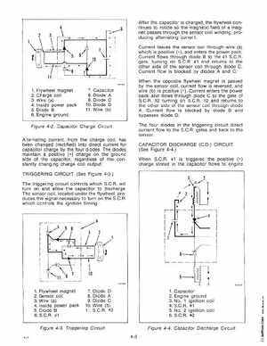
1Flywheel magnet 2Charge coil 3Wire (a) 4I nside power pack 5Diode 6Engine ground
7Capacitor 8Diode 9Diode 10Diode 11 Wire (b)
When the opposite flywheel magnet is passed by the sensor coil, current flow is reversedand wire (b) is positive (+) Current enters the power pack and flows through diode to the gate of S.C.R#2 turning on S.C.R#2 and returns to the other side of the sensor coil through diode ACurrent flow is blocked by diode Band bypasses diode DThe four diodes in the triggering circuit direct current flow to the S.C.Rgates and back to the sensorCAPACITOR DISCHARGE (C.D CIRCUIT (See Figure 4-4 When S.C.R#1 is triggered the positive (+) charge stored in the capacitor flows to engine