1978 Johnson 55 HP Outboards Service Manual, Page 47Get this manual
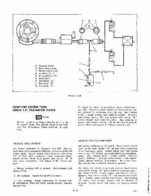
1Jumper wires 2Blue tester lead 3Black tester lead 4Position No.1 5Press button "A" 6Neon light 7Terminal "A" 8Terminal "B" 9Terminal "c"
Figure 4-25
IGNITION SYSTEM TESTS USING CDVOLTMETER TESTER
NOTE Before conducting these tests be sure to do the Spark Test, Key Switch Elimination Test and the Ohmmeter Tests starting on page 4-6
To check for short to ground, set meter (negative) and 500Remove black meter lead from cavity "D" and ground to armature plate groundSee Figure 4-26Crank engine and observe meterRemove lead from cavity "D" and insert into cavity "A Crank engine and observe meterAny reading on either test means charge coil is shorted to groundLocate short and repair or replace charge coil
SENSOR COIL OUTPUT TEST CHARGE COIL OUTPUT Set meter switches to Negative and 500Disconnect four wire connector between armature plate and power packInsert meter red lead probe into cavity "A" of four wire connector from armature plateInsert meter black lead probe into cavity "D" of four wire connectorSee Figure 4-26Crank engineaMeter reading 230 or higherGo to Sensor Coil Output TestbNo readingCheck for short to groundSet meter switches to "s" and 5Insert meter black lead probe into cavity "B" of four wire connector from armature plateInsert meter red lead probe into cavity "c" of four wire connector from armatureplateSee Figure 4-27Crank engine: observe meter readingreverse meter leads, crank engine: meter should indicate .3 or higherNo or low reading, check sensor coil for shorts to groundTo check for shorts to ground, remove black meter lead from cavity "B" and ground to armature plateSee Figure 4-27Crank engine and observe meterRemove lead from cavity "c" and insert into cavity "B Crank engine and observe meterAny reading on either test means sensor coil is shorted to groundLocate short and repair or replace sensor coil4-12