1978 Johnson 55 HP Outboards Service Manual, Page 43Get this manual
12345 Jumper wires Key switch Terminal "A" Terminal "B" Terminal "C"
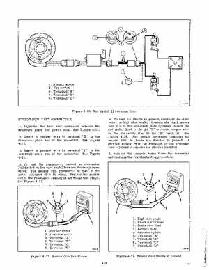
Figure 4-16Key Switch Elimination Test SENSOR COIL TEST (OHMMETER) aSeparate the four wire connector between the armature plate and power packSee Figure 4-15bInsert jumper wire to terminal "B" in the armature plate end of the connectorSee Figure 4-17cInsert jumper wire to terminal "C" in the armature plate end of the connectorSee Figure 4-17dTo test the resistance, connect an ohmmeter (calibrated on low ohm scale) between the two jumper wiresThe sensor coil resistance is good if the meter indicates 40 10 ohmsReplace the sensor coil if the resistance reading is not within this rangeSee Figure 4-17eTo test for shorts to ground, calibrate the ohmmeter to high ohm scaleConnect the black meter lead (-) to the armature plate (ground)Attach the red meter lead (+) to the "C" terminal jumper wire in the connector then to the "B" terminalSee Figure 4-18Any needle movement indicates the sensor coil or leads are shorted to groundA shorted sensor must be replaced, or the grounded lead repaired to remove the shorted conditionfRemove the jumper wires from the connector and continue the troubleshooting procedure12345678983399