1978 Johnson 55 HP Outboards Service Manual, Page 38Get this manual
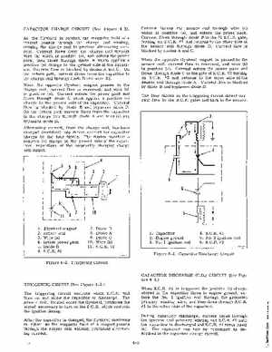
CAPACITOR CHARGE CIRCUIT (See Figure 4-2)As the flywheel is rotated, the magnetic field of magnet passes through the charge coil winding, causing the charge coil to produce alternating currentCurrent flows from the charge coil through wire (a) which is positive (+), and enters the power pack, then flows through diode which applies positive (+) charge to the ground side of the capacitorCurrent flow is blocked by diodes and COn the return path, current flows from the capacitor to the charge coil through diode and wire (b)When the opposite flywheel magnet passes by the charge coil, current flow is reversed, and wire (b) is positive (+)Current enters the power pack and flows through diode which applies positive (+) charge to the ground side of the capacitorCurrent flow is blocked by diode and bypasses diode DOn the return path current flows from the capacitor to the charge coil through diode and wire (a) and bypasses diode DAlternating current, from the charge coil, has been changed (rectified) into direct current for capacitor charge by the four diodesThe diodes maintain positive (+) charge on the ground side of the capacitor, regardless of the constantly changing charge coil output Current leaves the sensor coil through wire (a) which is positive (+), and enters the power packCurrent flows through diode to the #1 S.C.Rgate, turning on SCR#1 and returns to the other side of the sensor coil through diode DCurrent flow is blocked by diodes and CWhen the opposite flywheel magnet is passed by the sensor coil, current flow is reversed, and wire (b) is positive (+)Current enters the power pack and flows through diode to the gate of S.C.R#2 turning on SCR#2 and returns to the other side of the sensor coil through diode ACurrent flow is blocked by diode and bypasses diode DThe four diodes in the triggering circuit direct current flow to the S.C.Rgates and back to the sensor