1978 Johnson 55 HP Outboards Service Manual, Page 37Get this manual
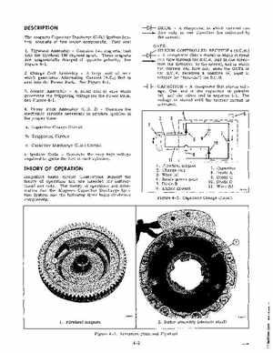
DESCRIPTION The magneto Capacitor Discharge (C.D Ignition System consists of five major componentsThey are: 1Flywheel AssemblyContains two magnets, cast into the flywheel 180 degrees apartThese magnets are magnetically charged of opposite polaritySee Figure 4-12Charge Coil Assemblylarge coil of wire which generates Alternating Current (A.C that is sent into the Power PackSee Figure 4-13Sensor Assemblysmall coil of wire which generates the triggering voltage for the Power PackSee Figure 4-14Power Pack Assembly (C.D2)Contains the electronic circuits necessary to produce ignition at the proper time: aCapacitor Charge Circuit bTriggering Circuit cCapacitor Discharge (C.D Circuit 5Ignition CoilsGenerate the very high voltage required to ignite the fuel in each cylinder
- component in which current can flow only in one direction (as indicated by the arrow)
GATE SILICON CONTROLLED RECTIFIER (S.C.R -1)1-component (like diode) in which current can flow through the S.C.Ronly in one direction (as indicated by the arrow), and in which the current can flow only when the GATE of the S.C.Rreceives positive (+) input to trigger (or "turn-on") the S.C.RCAPACITORcomponent that stores voltageOne end of the capacitor is positive (+), and the other end is negative (-)The voltage is stored until the trigger circuit is activated