1978 Johnson 4HP outboards Service Manual, Page 44Get this manual
SENSOR COIL OUTPUT TEST: switches to "S" and 5 Set meter
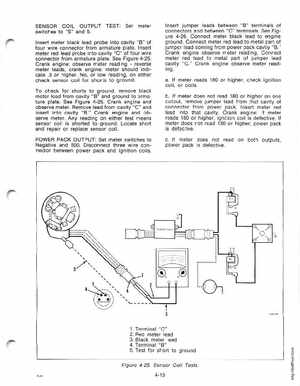
Insert meter black lead probe into cavity "B" of four wire connector from armature plateInsert meter red lead probe into cavity "C" of four wire connector from armature plateSee Figure 4-25Crank engine: observe meter readingreverse meter leads, crank engine: meter should indicate .3 or higherNo, or low reading, on either check sensor coil for shorts to groundTo check for shorts to ground, remove black meter lead from cavity "B" and ground to armature plateSee Figure 4-25Crank engine and .observe meterRemove lead from cavity "C" and insert into cavity "B Crank engine and observe meterAny reading on either test means sensor coil is shorted to groundLocate short and repair or replace sensor coilPOWER PACK OUTPUT: Set meter switches to Negative and 500Disconnect three wire connector between power pack and ignition coils
Insert jumper leads between "B" terminals of connectors and between "C" terminalsSee Figure 4-26Connect meter black lead to engine ground Connect meter red lead to metal part of jumper lead coming from power pack cavtiy "B Crank engine observe meter readingConnect meter red lead to metal part of jumper lead cavity "C Crank engine observe meter readingaIf meter reads 180 or higher, check ignition coil, or coilsbIf meter does not read 180 or higher on one output, remove jumper lead from that cavity of connector from power packInsert meter red lead into that cavityCrank engine: If meter reads 180 or higher, ignition coil is defectiveIf meter does not read 180 or higher, power pack is defectivecIf meter does not read on both outputs, power pack is defectivePOWER PACK