1978 Johnson 4HP outboards Service Manual, Page 40Get this manual
1Jumper wires 2Black tester lead 3Blue tester lead 4Position No2 5Hold button "B"
6Neon light 7Terminal "A" 8Terminal "B" 9Terminal "C" 10Terminal "0"
Figure 4- 19Charge Coil Output Test
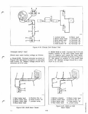
TRIGGER INPUT TEST Check neon tester battery voltage as followsaModel M-90Connect voltmeter as shown in Figure 4-20Set switch to position 4, and press load button "B Battery voltage should be minimum of 2-12 voltsbModel M-80 or S-80Connect the 1-1volt battery adapter to the neon tester black lead with (-) negative end toward the neon tester, and connect the voltmeter as shown in Figure 421 Set switch to position 3, and press road buttonBattery voltage should be minimum of 2-1 volts(+1