1978 Johnson 4HP outboards Service Manual, Page 35Get this manual
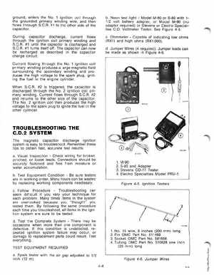
ground, enters the No1 ignition coil through the grounded primary winding wire, and then flows through S.CA#1 to the other side of the capacitorDuring capacitor discharge, current flows through the ignition coil primary winding and S.C.R#1 until the capacitor is discharged and S.C.A#1 turns itself offThe capacitor can now be recharged as described in the capacitor charge circuitCurrent flowing through the No.1 ignition coil primary winding produces large magnetic field surrounding the secondary winding and produces the high voltage to the spark plug, igniting the fuel in the engine cylinderWhen S.CA#2 is triggeredthe capacitor is discharged through the No.2 ignition coil primary winding Current flows through S.C.R#2 and returns to the other side of the capacitorThe No2 ignition coil then produces the high voltage to the spark plug to ignite the fuel in the other cyl nder bNeon test lightModel M-80 or S-80 with 11 volt battery adapter, or Model M-90 (no adapter required) or Stevens or Electro Specialties C.DVoltmeter TesterSee Figure 4-5cOhmmeterCapable of indicating low ohms (RX1) and high ohms (RX1,000)dJumper Wires (4 required)Jumper leads can be made as shown in Figure 4-6