1978 Johnson 2HP outboards Service Manual, Page 32Get this manual
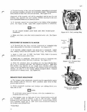
4-7 aCorrect locating of the coil and lamination assemblies is governed by machined mounting surfaces on the armature plateCoil lamination heels should be flush with machined surfacesSee Figure 4-16Alignment of the magneto coil will be simplified with the use of coil locating ring (special tool part number 317001) machined to fit over three machined bosses on the armature platebIf removed, connect the ground lead to the bottom of the armature plateSee Figure 4-15BApply OMC Liquid Neoprelle to connection IlIT,jJ;{U NOTE
Do not connect breaker point leads until after breaker point adjustmentcMake sure that new oiler wick is installed under coilSee Figure 4-15A
WITH COIL LAMINATION HEELS FLUSH AGAINST RINGTIGHTEN SCREWS
Figure 4-16Coil Locating Ring
REASSEMBLY OF MAGNETO TO MOTOR
aIf flywheel key has been removed, reassemble to crankshaft with outer edge parallel to centerline of crankshaftSee Figure 4-17 bIf removed, install magneto cam drive pin in crankshaftInstall cammaking certain that side marked "TOP" is upSee Figure 4-15AcApply light coat of OMC Sea-Lube Moly Lube to the inside diameter of the armature plate linerdInstall liner on crankcaseBoss will fit groove in crankcase only when curved side of liner tab faces crankcaseSee Figure 4-7ePlace the armature plate in position over the liner with the liner tab in slot in armature plate hubSee Figures 4-6 and 4-7Make sure that throttle cam follower is not caught under throttle control camInsert screw and tighten just enough to hold armature plate in selected position yet allow it to be turned without excessive effortConnect ground wire to exhaust coverSee Figure 4-5CAM PI FLYWHEEL KEY