1978 Johnson 175, 200, 235 HP Outboard Service Manual, Page 163Get this manual
3Remove locknut and washer and disconnect throttle control cable from throttle leverSee Figure 8-54Remove locknut, washer and shift control cable from shift leverSee Figure 8- 55Loosen anchor block clamp screws and swing clamps asideRemove the rubber grommet from front of lower motor cover, and disengage from cablesSee Figure 8-6 6Remove cable clamps attaching cable(s) to boat tive locationThis is done by first turning the clamp screw, reached thru access hole in rear of control box, with 332" Allen wrench until it just touches the wireNext advance the clamp screw one turn onlyThis will kink the wire sufficiently to locate it in the caSing guideFinally, install the anchor screw from the front and tighten securelySee Figure 8-7
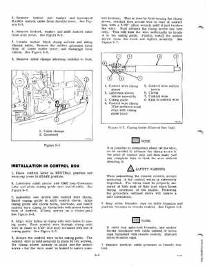
1Control wire clamp
screw 2Lubricate sleeve before assembly 3Casing guide 4Control wire clamp (Flat surfaces must align with caSing guide hole)
5Control wire anchor screw 6Clevis 7Control wire 8Kink in control wire
Figure 8-7Casing Guide (Control Box End)