1978 Johnson 175, 200, 235 HP Outboard Service Manual, Page 162Get this manual
For control cable or other component replacement, control box must be unfastened from boat and loosen front control wire clamp screw(s)Thru access hole in pack of control box, loosen rear clamp screw(s)See Figure 8-42Lift control cable trunnion(s) out of control box and disengage wire(s) from casing guide(s)See Figure 8-4
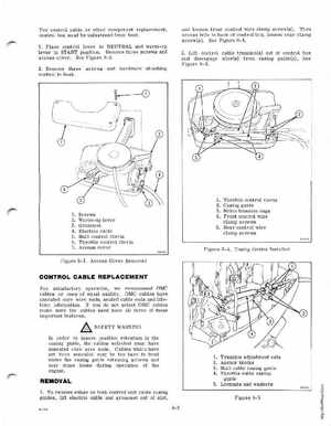
1Place control lever in NEUTRAL and warm-up lever in START positionRemove three screws and access coverSee Figure 8-32Remove three screws and hardware attaching control to boat
1234567
Screws Warm-up lever Grommet Electric cable Shift control clevis Throttle control clevis Access cover
Throttle control clevis Casing guide Nylon trunnion caps Front control wire clamp screws 5Rear control wire clamp screws
Figure 8-4Casing Guides Installed
Figure 8-3Access Cover Removed