1978 Johnson 175, 200, 235 HP Outboard Service Manual, Page 157Get this manual
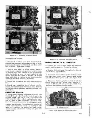
Figure 7-37Checking Rectifier Diodes RECTIFIER ON ENGINE Figure 7-38Checking Alternator Stator
1Discormect rectifier leads from terminal blockConnect one ohmmeter (HI ohms scale) lead to either yellow or yellowgray rectifier lead, and other meter lead to groundNote meter reading2Reverse test leadsor press polarity button if meter is so equipped, and again note meter readingAn infinite (very high) reading in both checks indicates the diode is openA zero reading in both checks indicates the diode is shortedA normal diode will show reading in one direction and no reading in the other direction (co) infinity3Repeat this procedure with other rectifier yellow lead4Repeat test, cormecting meter between rectifier yellow lead and rectifier redpurple leadBetween yellowgray stripe rectifier lead and rectifier red purple lead
REPLACEMENT OF ALTERNATOR
If windings are found to have failed, the stator as-
sembly must be replaced
Proceed as follows:
aRemove flywheel, using Universal puller (Special Tool #378103)See Section 5bDiscormect stator and charge coil leads at terminal board and Power Packs Remove four screws and lift stator from power headSee Figure 7-39cPlace new stator in position and attach with four screws dipped in OMC Screw LockTighten to torque of 120 to 144 inch-pounds (14.0-16.0 N.m)Reconnect stator and charge coil leads