1978 Johnson 175, 200, 235 HP Outboard Service Manual, Page 90Get this manual
bIf removed, place lower bearing retainer plate over end of crankshaftUsing an arbor press, press ball bearing onto lower journalOil ball bearing and install retaining ringSee Figure 5-59cInstall new "0" rings on lower crankcase head and place crankcase head in pOSition aligning holes with the bearing retainer plateSee Figure 5-59 gApply coat of OMC Needle Bearing Grease (Part Number 378642) to connecting rod bearing areaPlace one retainer half and eight needle bearings on each rodSee Figure 5-60
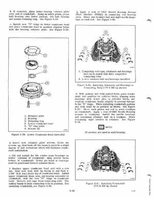
1Connecting rod caps, retainers and bearings laid out to match with their respective connecting rods 2Lowe retainer half and bearings installed
Figure 5-60Installing Retainers and Bearings in Connecting Rods (175200 hp shown) hWith pistons and rods pushed down, place crankshaft into position on cylinder block, aligning main bearings with dowel pins in cylinder block, and rotating crankcase heads slightly to prevent damage to the "0" ringsWhile installing crankshaft, pistons and rods must be in position as shownSee Figure 5-61Move each piston and rod to meet crankpin on crankshaftApply coat of OMC Needle Bearing Grease to crankpinsInstall two needle bearings and remaining retainer half on crankpinPlace remaining eight needles in retainerSee Figure 5-62NOTE