1978 Johnson 175, 200, 235 HP Outboard Service Manual, Page 69Get this manual
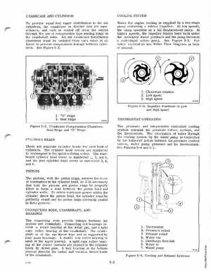
CRANKCASE AND CYLINDERS To provide equal fuel vapor distribution to the six cylinders, the crankcase is divided into six equal VOlumes, and each is sealed off from the others through the use of compression type sealing rings on the crankshaft websAll six crankcase distribution chambers must be isolated from each other at all times to prevent compression leakage between cylindersSee Figure 5-2 COOLING SYSTEM Water for engine cooling is supplied by two-stage pump containing rubber impellerAt low speeds, the pump operates as full displacement pump At higher speeds, the impeller blades bend back under the increased water pressure and the pump becomes centrifugal action pumpSee Figure 5-3For water circulation see Water Flow Diagram in back of manual
1Clockwise rotation 2Low speed 3High speed
Figure 5-3Impeller Positions at Low and High Speed