1978 Johnson 175, 200, 235 HP Outboard Service Manual, Page 61Get this manual
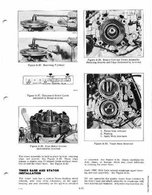
Figure 4-29Sensor Coil and Timer Assembly Retaining Screws and Clips (Indicated by Arrows) Figure 4- 26Removing Flywheel
lIft" ell
Figure 4-27Disconnect Stator Leads Indicated by Broad Arrows
1Timer base retainer 2Bushing 3Apply Moly lube here
Figure 4-30Timer Base Removed Figure 4- 28Four Stator Screws (Indicated by Arrows) The timer assembly is held in place by four retaining clips and screwsSee Figure 4-29 These clips engage plastic ring (T-shaped cross section) which fits around the timer baseSee Figure 4-30