1978 Johnson 175, 200, 235 HP Outboard Service Manual, Page 53Get this manual
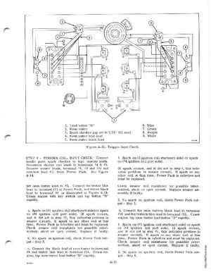
1Load button "B"
2345Neon tester Spark checker gap set to 716" (11 mm) Neon tester blue lead Neon tester black lead Figure 4-14Trigger Input Check STEPTRIGGER COIL INPUT CHECK: Connect needle point spark checker to high tension leadsReconnect charge coil leads to terminals #4#5Remove sensor leads, terminal #8, #9 and #10 and common lead #1 from Power PackSee Figure 4-14Set neon tester knob to #3Connect the tester blue lead to terminal #11 of Power Packand tester black lead to terminal #8 as illustrated in Figure 4-14Crank engine with key switch and tap buttonB" rapidlyaSpark on (#1 ignition coil starboard side) or spark on (#6 ignition coil port side)(If spark occurs, and it did not in step #1, this indicates problem in sensor circuit)If spark on any other coil at this timePower Pack is defective and must be replacedCheck sensor coil resistance for possible intermittent, short or open circuitReplace if faultybNo spark on ignition coil, check Power Pack outputStep 5cConnect the black lead of neon tester to terminal #9 and tester blue lead to terminal #11Crank engine, tap neon tester load button "B" rapidlyE,JV6