1978 Evinrude Outboards 9.9/15HP Service Manual, Page 51Get this manual
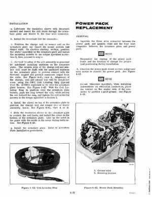
INSTALLATION aLubricate the insulation sleeve with Isopropyl alcohol and insert the coil leads through the armature plate and sleeve to the four wire connectorbInstall the terminals into the connectorcPosition the charge coil or sensor coil on the armature plate and insert the mount screws just finger tightOn electric starting models, position the stator assembly on the armature plate and install the mounting screws to the torque specified in Section 2, then proceed to step edCorrect locating of the coil assembly is governed by machined mounting surfaces on the armature plateThe outside edge of the charge coil and sensor coil must be flush with the machined surfaces on the armature plate to prevent contact with the flywheel magnet and provide maximum output from the coilsSee Figure 4-41, view AAlignment of the charge, coil and sensor coil will be simplified when using the OMC Coil Locating Ring (Special Tool No317001) machined to fit over the armature plate bossesSee Figure 4-42With the Coil Locating Ring in position over the armature plate bosses, push the ring toward the coil, while pulling the coil toward the ring, and tighten the coil mounting screws to the torque specified in Section 2eInstall the clamp on top of the armature plate to position the charge coil and sensor coil or stator assembly leadsSee Figure 4-41, view or fSlide the insulation sleeve to the armature plate to protect the coil leads, and install the cover on the bottom of the armature plateLine up the notch in the plate with the notch on the cover during installationSee Figure 4-40 POWER PACK REPLACEMENT