1978 Evinrude Outboards 9.9/15HP Service Manual, Page 40Get this manual
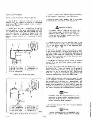
TRIGGER INPUT TEST Check neon tester battery voltage as follows: aModel M-90Connect voltmeter as shown in Figure 4-22Set switch to position 4, and press load button "B Battery voltage should be minimum of 2-12 volts bModel M-80 or S-80Connect the 1-12 volt battery adapter to the neon tester black lead with (-) negative end toward the neon tester, and connect the voltmeter as shown in Figure 4-23Set switch to position 3, and press load button "B Battery voltage should be minimum of 2-12 volts cInsert jumper wire between the "A" terminals of both four wire connectorsSee Figure 4-24dInsert jumper wire between the "D" terminals of both four wire connectorsSee Figure 4-24
SAFETY WARNING TO AVOID POSSIBLE SHOCK HAZARDS, DO NOT TOUCH THE TERMINAL ENDS OF THE JUMPER WIRES WHILE MAKING CONNECTIONS TO THE POWER PACK, OR WHEN CRANKING THE ENGINE
eAttach jumper wire to the blue lead of the neon tester, then insert the jumper wire to terminal "B" in the power pack end of the four wire connectorSee Figure 4-24
fConnect jumper wire to the positive (+) side of the battery adapter, (on M-90 neon testers, connect the jumper wire directly to the black 'lead of the tester), and insert the jumper wire to terminal "C" in the power pack end of the four wire connectorsSee Figure 4-24