1977 Evinrude 4HP Outboards Service Manual, PN 5303, Page 42Get this manual
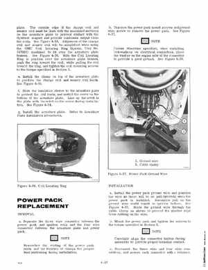
plateThe outside edge of the charge coil and sensor coil must be flush with the machined surfaces on the armature plate to prevent contact with the flywheel magnet and provide maximum output from the coilsSee Figure 4-35Alignment of the charge coil and sensor coil will be simplified when using the OMC Coil Locating Ring (Special Tool No317001) machined to fit over the armature plate bossesSee Figure 4-36With the Coil Locating Ring in position over the armature plate bosses, push the ring toward the coil, while pulling the coil toward the ringand tighten the coil mounting screws to the torque specified in Section 2eInstall the clamp on top of the armature plate to position the charge coil and sensor coil leadsSee Figure 4-35fSlide the insulation sleeve to the armature plate to protect the coil leadsand install the cover on the bottom of the armature plateLine up the notch in the plate with the notch on the cover during installationSee Figure 4-34 bUnscrew the power pack mount screws and ground wire screw to remove the power packSee Figure 4-37NOTE Unless otherwise specified, when installing lockwashers on electrical connectorsplace the washer on the engine side of the connector to provide good groundSee Figure 4-38