1977 Evinrude 4HP Outboards Service Manual, PN 5303, Page 35Get this manual
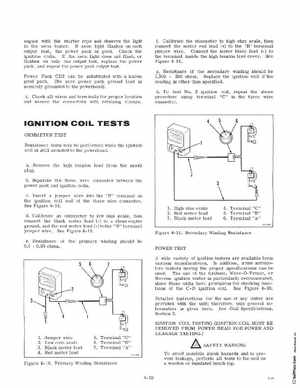
engine with the starter rope and observe the light in the neon testerIf neon light flashes on each output test, the power pack is goodCheck the ignition coilsIf the neon light does not flashor flashes on only one output test, replace the power pack, and repeat the power pack output testPower Pack CD2 can be substituted with known good pack(Be sure power pack ground lead is securely grounded to the powerhead)iCheck all wires and terminals for proper location and secure the connectors with retaining clamps fCalibrate the ohmmeter connect the meter red lead jumper wireConnect the the terminal inside the high Figure 4-19
to high ohm scale, then (+) to the "B" terminal meter black lead (-) to tension lead coverSee
gResistance of the secondary winding should be 1,3 00 200 ohmsReplace the ignition coil if the reading is other than speCifiedhTo test No2 ignition coil, repeat the above procedure using terminal "C" in the three wire connector
IGNITION COIL TESTS
OHMMETER TEST Resistance tests may be performed while the ignition coil is still mounted to the powerheadaRemove the high tension lead from the spark plugbSeparate the three wire connector between the power pack and ignition coilscInsert jumper wire into the "B" terminal on the ignition coil end of the three wire connectorSee Figure 4-18dCalibrate an ohmmeter to low ohm scalethen connect the black meter lead (-) to clean engine ground, and the red meter lead (+) to the "B" terminal jumper wireSee Figure 4-18eResistance of the primary winding should be 0.1 0.05 ohms