1977 Evinrude 4HP Outboards Service Manual, PN 5303, Page 30Get this manual
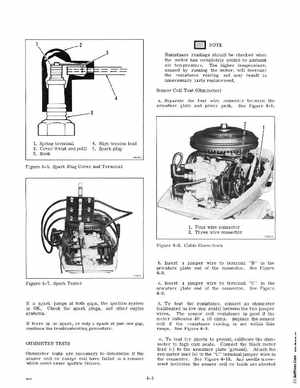
NOTE Resistance readings should be checked when the motor has completely cooled to ambient air temperatureThe higher temperature, caused by running the motor, will increase the resistance reading and may result in unnecessary parts replacementSensor Coil Test (Ohmmeter) aSeparate the four wire connector between the armature plate and power packSee Figure 4-8 1Spring terminal 2Cover (twist and pull) 3Hook
4High tension lead 5Spark plug
Figure 4-6Spark Plug Cover and Terminal
1Four wire connector 2Three wire connector
Figure 4-8Cable Connectors
bInsert jumper wire to terminal "BTl in the armature plate end of the connectorSee Figure 4-9cInsert jumper wire to terminal "C" in the armature plate end of the connectorSee Figure 4-9dTo test the resistance, connect an ohmmeter (calibrated on low ohm scale) between the two jumper wiresThe sensor coil resistance is good if the meter indicates 40 10 ohmsReplace the sensor coil if the resistance reading is not within this rangeSee Figure 4- 9eTo test for shorts to ground, calibrate the ohmmeter to high ohm scaleConnect the black meter lead (-) to the armature plate (ground)Attach the red meter lead (+) to the "C" terminal jumper wire in the connectorSee Figure 4-10Any needle movement indicates the sensor coil or leads are shorted