1977 Evinrude 4HP Outboards Service Manual, PN 5303, Page 28Get this manual
After the capacitor is charged, the flywheel continues to rotate so the magnetic field of magnet passes through the sensor coil winding, producing alternating currentCurrent leaves the sensor coil through wire (a) which is positive (+), and enters the power packCurrent flows through diode to the #1 S.C.Rgate, turning on S.C.R#1 and returns to the othe side of the sensor coil through diode DCurrent flow is blocked by diodes and CWhen the opposite flywheel magnet is passed by the sensor coil, current flow is reversed, and wire (b) is positive (+)Current enters the power pack and flows through diode to the gate of S.C.R#2 turning on S.C.R#2 and returns to the othe side of the sensor coil through diode ACurrent flow is blocked by diodes and B
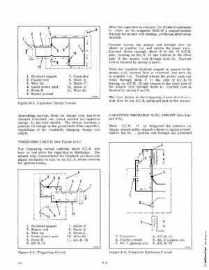
2Charge coil 3Wire (a)
1Flywheel magnet
7Capacitor 8Diode 9Diode C
10Diode 11Wire (b)
4Inside power pack 5Diode 6Engine ground
Figure 4-2Capacitor Charge Circuit
The four diodes in the triggering circuit dire ct current flow to the S.C.Rgates and back to the nsor
Alternating current, from the charge coil, has been changed (rectified) into direct current for capacitor charge by the four diodesThe diodes maintain positive (+) charge on the ground side ofthe capacitor, regardless of the constantly changing charge coil outputTRIGGERING CIRCUIT (See Figure 4-3 The triggering circuit controls which S.CRwill turn on and allow the capacitor to dischargeThe sensor coil, located under the flywheelproduces the signal necessary to turn on the S.C.Rwhich controls the ignition timing