1976 Evinrude 40HP outboards Service Manual, Page 20Get this manual
ALIGNING RECESSES
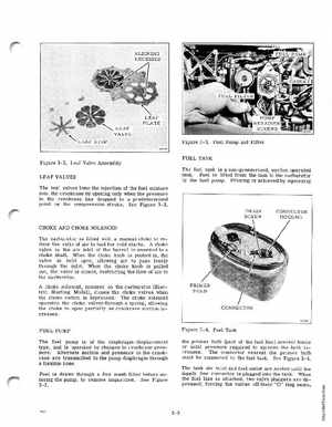
Figure 3-3Fuel Pump and Filter FUEL TANK The fuel tank is non-pressurized, suction operated tank Fuel is lifted from the tank to the carburetor by the fuel pumpPriming is achieved by squeezing
Figure 3-2Leaf Valve Assembly LEAF VALVES The leaf valves time the injection of the fuel mixture into the crankcase by opening only when the pressure in the crankcase has dropped to predetermined pOint on the compression strokeSee Figure 3-2
DRAIN SCREW
CONNECTOR HOUSING
CHOKE AND CHOKE SOLENOID The carburetor is fitted with manual choke to reduce the ratio of air to fuel for cold startsA choke valve in the air inlet of the barrel is mounted to choke shaftWhen the choke knob is pushed in, the valve is held open, allowing air to pass freely through the inletWhen the choke knob is pulled out, the valve is closed, restricting the flow of air to the carburetorA choke solenoid, mounted on the carburetor (Electric Starting Model), closes the choke valves when the choke switch is depressedThe choke solenoid operates the choke valves through spring, allowing the choke to open partially as crankcase suction increases FUEL PUMP The fuel pump is of the diaphragm-displacement type, and is operated by changes in crankcase pressureAlternate suction and pressure in the crankcase are transmitted to the pump diaphragm through flexible hoseFuel is drawn through fine mesh filter before entering the pump, to remove impuritiesSee Figure 3-3