1976 Evinrude 200 HP Outboards Service Manual, PN 5199, Page 164Get this manual
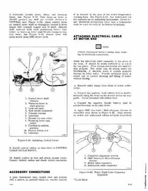
8Lubricate throttle lever, detent and warm-up leverSee Figure 8-19With warm-up lever in ST ART position and shift and throttle clevises in NEUTRAL (see Figure 8-19), place control lever on control lever shaft so triangular recess in lever aligns with triangle shaped end of shaftSqueeze shift lock-out knob while positioning leverCam roller on warm-up lever must fit into recess in control leverSee Figure 8-19Secure lever with Allen screw using OMC Screw Lock It is located in the area of the motor temperature warning hornSee Figure 8-13See tachometer kit for instructions on connecting tachometerPower for any electrical accessories other than tachometer must be made directly at the battery terminals
A TTACHING ELECTRICAL CABLE AT MOTOR END
Ui,!!!i!l l; NOTE
Always disconnect battery cables when working on electrical connectionsRoute the electrical cable assembly to the stern of the boatIt should be neatly fastened in an out of the way placeFour clamps and screws are used for this purposeThe cable may be strung under the floorboards, if desired, since it resists possible damage by bilge waterProvide sufficient slack at motor end to permit steering and tilting of motor without bindingaRemove cable clamp from front of lower motor coverbConnect the positive (red) battery lead to starter solenoid using the decal on the starter motor as your guideCover terminal with rubber bootcConnect the negative (black) battery lead to ground terminal on by-pass coverdApply OMC Sea-Lube Multi-Purpose Grease to connector area shown in Figure 8- 20Align arrows on motor and instrument cables and push connectors