1976 Evinrude 200 HP Outboards Service Manual, PN 5199, Page 160Get this manual
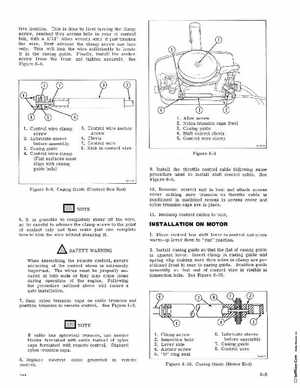
tive locationThis is done by first turning the clamp screw, reached thru access hole in rear of control box, with 3 32" Allen wrench until it just touches the wireNext advance the clamp screw one turn onlyThis will kink the wire sufficiently to locate it in the casing guideFinally, install the anchor screw from the front and tighten securelySee Figure 8-8 1Control wire clamp screw 2Lubricate sleeve before assembly 3Casing gUide 4Control wire clamp (Flat surfaces must align with casing guide hole)
5Control wire anchor screw 6Clevis 7Control wire 8Kink in control wire
Allen screw Nylon trunnion caps (two) Casing guide Shift control clevis Control wire clamp
Figure 8-9 9Install the throttle control cable following same procedure used to install shift control cableSee Figure 8-510Remount control unit in boat and attach access cover making sure trunnion on throttle cable is positioned in machined recess in access cover and nylon trunnion caps are in place11Reclamp control cables to boat