1976 Evinrude 200 HP Outboards Service Manual, PN 5199, Page 67Get this manual
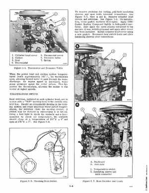
To remove switches for testing, pull back insulating sleeves and open knife terminal connectionsSee Figure 5-7, view and BRemove cylinder head covers and switchesSee Figure 5-8On installation, clean gasket surfaces thoroughlyApply OMC Gasket Sealing Compound lightly to both gasket surfacesAlso apply the same sealing compound to top surface of heat switch grommet and again after cover has been installedInstall cylinder head cover using new gasketReconnect heat switch leads and slide insulating sleeves over connections 1234
Cylinder head cover Gasket Seal Thermostat
5Thermostat cover 6Pressure valve 7Spring
Figure 5-5Thermostat and Pressure Valve When the power head and cooling system temperatures reach approximately 145F the thermostats open, allowing heated water to pass through the water dischargeAs engine speed is increased, water pump pressure opens the relief valvesThis bypasses the thermostats, allowing the engine to run cooler at higher speedsrEMPERATURE SWITCH Heat switches, installed in each cylinder head, are in series with "HOT" warning horn in the remote control boxShould an irregularity develop in the cooling system and cause abnormal water jacket temperatures, the' switches close the warning circuitA switch may be checked by submerging it in hot oilUSing test light to check the contacts and thermometer to check oil temperature, the contacts should close at temperature of 211 and open at 175F 7See Figure 5-6AStarboard