1976 Evinrude 200 HP Outboards Service Manual, PN 5199, Page 58Get this manual
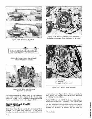
Figure 4-29Sensor Coil and Timer Assembly Retaining Screws and Clips (Indicated by Arrows) Figure 4- 26Removing Flywheel
Figure 4-27Disconnect Stator Leads Indicated by Broad Arrows
1Delrin ring 2Bushing 3Apply Moly lube here
Figure 4-30Timer Base Removed Figure 4- 28Four Stator Screws (Indicated by Arrows) The timer assembly is held in place by four retaining clips and screwsSee Figure 4-29These clips engage Delrin ring (T-shaped cross section) which fits around the timer baseSee Figure 4-30or retardedSee Figure 4-30Check carefully for dirt, chips, or damage which may cause difficulty in rotating the timer baseApply OMC Sea- Lube Moly Lube around crankcase upper bearing and seal assemblySee Figure 4-30Oil and assemble the Delrin retainer to the timer base and attach assembly to crankcase with four screws and washersIf flywheel key has been reTrade Mark